domingo, 15 de junio de 2014

Packages


dip
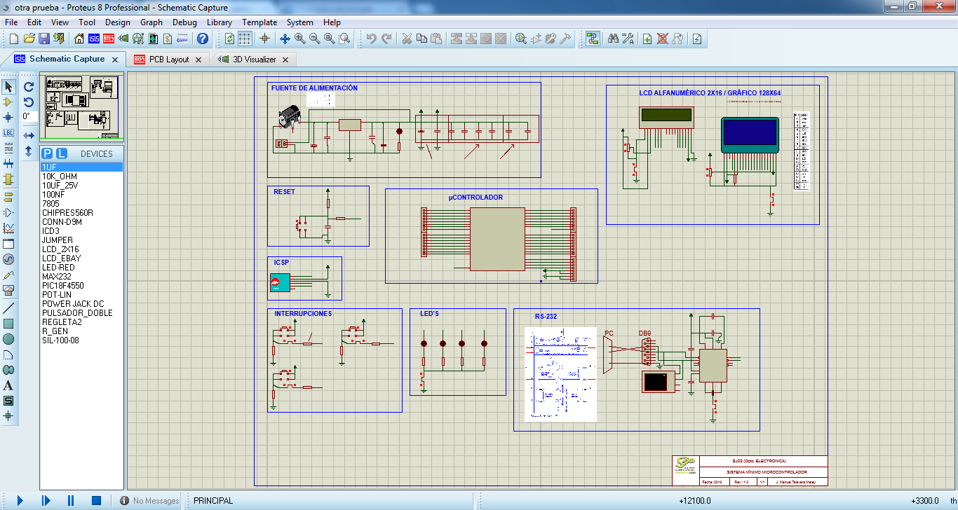
DIP: The pins extend along the encapsulated (both sides) and has like everyone else a notch indicating pin number 1. This basic encapsulation was the most widely used a few years ago and remains the favorite when assembling PCB split lovers home electronics due to their size making it easy to weld. Today, the use of this encapsulation (industrially) merely UVEPROM and sensors.
sipSIP: The pins extend along one side of encapsulation and mounted vertically on the board. The consequent reduction in mounting area allows for higher mounting density that obtained with DIP.
pgaPGA: The multiple connector pins are located on the bottom of the package. This type is used for PC CPUs and was the main choice when considering efficiency pin-space-capsule before the introduction of BGA. The PGAs were made of plastic and ceramic, however the plastic is currently the most widely used, while the ceramic PGAs are used for a small number of applications.
sopSOP: The pins are arranged in two sections longer and extend in a form called "gull wing formation", this is the main type of surface mount and is widely used especially in the areas of microcomputers, memories and analog IC utilizing a relatively small number of pins.
tsopTSOP: Just a slimmer version of the encapsulated SOP.
qfpQFP: It is the upgraded version of the encapsulated SOP, where the connector pins extending along all four edges. This is currently the most popular supeficial encapsulated assembly, because it allows a greater number of pins.
sojSOJ: The tips of the pins extend from the two longest edges leaving half separation as if they were two encapsulated one. Receives this name because the pins to the letter "J" look when viewed from the side. They were used in SIMM memory modules.
qfjQFJ: As the encapsulated QFP, the pins extending from the four edges edges.
qfnQFN: QFP is similar to, but with the pins on the four edges of the bottom of the package. This can be encapsulated in models of low density or high density.
tcpTCP: The silicon chip is encapsulated in the form of film tapes can be produced in different sizes, the encapsulation may be folded. They are mainly used for the LCD drivers.
bgaBGA: External terminals, solder spheres reality, are located in table format at the bottom of the package. This encapsulated can get a high density of pins, compared with other encapsulated as QFP, BGA has the lowest probability of defective mounting the boards.
lgaLGA: It is an enveloped electrodes aligned in array form on the bottom. It is suitable for operations where high speed is required due to low inductance. Furthermore, in contrast to the BGA solder spheres no whereby the mounting height can be reduced.

sábado, 14 de junio de 2014

PCB Designing by photolitography

In this post i will explain how to make a PCB by photolitography.

At first, we start designing a scheme in proteus:


The next step is print this scheme. For do this, we click in Output/Print Layout.

First we print bottom copper:


And next repeat this with top copper.

The next step is make the drill. For do this, clik Output/Generate Gerber/Excellon files, and select the drill.
When we have Drill file, we go to the CNC machine and we repeat the same in the other post: PCB Designing with CNC, and make the holes.

To do this PCB, we will need a special  PCB cupper board:


When we have the holes, we have to go to special room, with special light to do this board because if it gives natural light to the board, be damaged.

Being in the special room, remove the blue protective plastic, placed schemes we print before matching the holes.

Now we need a special machine that emits ultraviolet light to insolation, and expose the board a minimum of 350 seconds.


To make tracks, we have to make a mixture of water, hydrochloric acid and hydrogen peroxide in equal parts, so that the acid slowly peel off the protective layer.

Gradually we see that the acid does its work and begin to see the tracks.

This process takes about five minutes.


Caution! if you expose too long plate with acid, lose tracks and that plate will not serve.

When you see the tracks and serigraphy are clearly defined, take the plate and wash with warm water.

And finally, we only have to solder the components and enjoy our PCB made ​​by photolitography.

viernes, 13 de junio de 2014

PCB Designing with CNC

This post is dedicated to explain how to do a PCB with a CNC machine ProtoMat ® S62 LPKF with our design in Proteus.


At first we have to design a microcontroller system in Proteus.


When we just design this, we have to go Ares and connect all to have the final version of our PCB.


Is time to export the archives we will need to use in the CNC program. This archives called GERBER/EXCELLON, and contain the necessary information to the CNC coordinates must follow to make tracks, roads, drill holes...

Click OUTPUT/GENERATE GERBER/EXCELLON FILES and will leave a notice saying this:


Click "Yes", and we will see this:


Click in "Close" and a window appears where we will generate our archives.


We tick archives we want to export and click "Ok". Now we have GERBER/EXCELLON files in the folder we choosen.


Now we have five text documents with the information CNC will need to do our PCB. We have to take all except the "READ ME" archive, and open the next program: Circuit Cam.

When u click in IMPORT, a window like this appear, and u have to select GERBER/EXCELLON files.


Once selected, a new window appears us with the layers we’ve added, and we will change the “Layer” option, setting the layer corresponding to each file in “File name”, as seen in the pictures.


The next step is click in "Contour routing" and we have to select the layer “Cutting outside”, modified to our liking, we will execute the changes.


Now click in Tool path/Isolate and first isolation of the bottom, we will leave the default tools, it is important that you have to change the settings to 2mm wide. Finish it to execute the changes and repeat the proccess with the top.


Now open the Board Master 5.0 program and click "Export".  The program will open the file automatically.

The first step is put the drill tools in the machine which the program indicate you clicking in the option to open the toolbox.


When we do this, the next step is select the MarkingDrills option, click in "All+" and click Start. The machine will start to do the drill.

When it finish, the next step is click in MillingBottom, "All+" and "Start". When it finish,turn to the plate forward and repeat it with the MillingTop option.

Now we have to select "CuttingOutside" option, click "All+" and Start, and now we have our PCB ready, but without the components.

The next step is to solder the components.


And now we have our PCD ready to use!

miércoles, 11 de junio de 2014

(MPLAB-IDE) Analog/Digital Converter PCF8591 I2C

In this post i will explain how to use the analog/digital converter with PCF8591 comunicating with PIC18F4550 by I2C.

The secuence to read of the I2C communication is:

START->ADDRESS W->CONTROL BYTE->REPEATED START->ADDRESS R->DATA BYTE

And knowing this i made the program:


//////////////////////////////////////////////////////
// CABECERA /////////////////////////////
//////////////////////////////////////////////////////
#include<18f4550.h>
#fuses INTHS,MCLR
#use delay(internal=8mhz)
#use i2c(Master,sda=PIN_B0,scl=PIN_B1)
#use rs232(baud=9600,parity=N,xmit=pin_c6,rcv=pin_c7,bits=8)
#include <LCD_flexible.c>
//////////////////////////////////////////////////////
// VARIABLES GLOBALES ////////
//////////////////////////////////////////////////////
char nombre[20];  
char enter;
int direccion=0b00000000;
int a,escribir;
int incremento;
//////////////////////////////////////////////////////
// FUNCIONES ///////////////////////////
//////////////////////////////////////////////////////
#INT_RDA 
void rda_int()
{
    enter = getchar();
putc(enter);

if(enter==13  || a==20)
{
escribir=1;nombre[a]=0;
}  

else 
  {
  nombre[a]=enter; 
a++;
 
}
//////////////////////////////////////////////////////
// PROGRAMA PRINCIPAL //////
//////////////////////////////////////////////////////
void main()
{

 a=0;
 lcd_init();
 enable_interrupts(INT_RDA); 
 enable_interrupts(GLOBAL);
 escribir=0;
 puts( "Escribe tu nombre" ); 
 while(escribir==0)
 {}
  puts("Pulsa enter para grabar en la memoria");
  enter = getchar();
  if(enter!=13)
  {
  escribir=0;
  }  
  
  else
  for (incremento=0;incremento<15;incremento++) 
  {
 
   if (nombre[incremento]==0)
   break;
   
   i2c_start();  
   i2c_write(0b10100000); 
   i2c_write(0b00000000);  
   i2c_write(direccion);
   i2c_write(nombre[incremento]);
   i2c_stop();
   direccion ++;
   
   lcd_gotoxy(1,1);
   printf(lcd_putc," MEMORIA ");
   lcd_gotoxy(2,2);
   printf(lcd_putc,"%s",nombre); 
   delay_ms(2); 
  }

}
//////////////////////////////////////////////////////

And this is the scheme in Proteus:


lunes, 9 de junio de 2014

(MPLAB-IDE) Digital/Analog converter MCP3204 SPI

In this practice I am going to explain how to read an analog value from a knob and convert it to a digital signal to display these real value in a LCD screen using the SPI serial interface to comunicate the DAC with the PIC18F4550.

To perform this conversion, I will use a MCP3204 configured with SPI interface. This device needs a library (MCP3204.c) to be programmed more easily.


The first step is build a scheme in Proteus:


Program:


I started configurating the library with the pins I want to use:


#define MCP3204_CLK PIN_B1
#define MCP3204_DOUT PIN_B0
#define MCP3204_DIN PIN_C7
#define MCP3204_CS PIN_A0


And this is the code i used:


//////////////////////////////////////////////////////////////////////////

// CABECERA /////////////////////////////////////////////////
//////////////////////////////////////////////////////////////////////////
#include <18f4550.h>
#fuses XT,MCLR
#use delay(clock=20000000)
#include <LCD_flexible.c>
#include <C:\Users\Talavera\Desktop\Clase\New Folder\Luis\MPLAB\MCP_3204_SPI\mcp3204.c>
//////////////////////////////////////////////////////////////////////////
// VARIABLES GLOBALES ///////////////////////////
//////////////////////////////////////////////////////////////////////////
long int valor;
float voltaje;
//////////////////////////////////////////////////////////////////////////
// FUNCIONES ////////////////////////////////////////////////
//////////////////////////////////////////////////////////////////////////

//////////////////////////////////////////////////////////////////////////

// PRINCIPAL //////////////////////////////////////////////////
//////////////////////////////////////////////////////////////////////////
void main()
{
lcd_init();
adc_init();
lcd_putc("CAD MCP 3204");
for(;;)
{
valor = read_analog(0);
voltaje = (valor*5.0)/4096;
LCD_GOTOXY(1,2);
printf(lcd_putc,"Voltaje = %f V", voltaje);
}

}
//////////////////////////////////////////////////////////////////////////

Is time to simulate our program in Proteus and see the results:


We can see in the LCD screen how this voltaje value matches with the voltimeter value we control with a knob.

lunes, 2 de junio de 2014

(labVIEW + Arduino) Temperature and motor control with light

Here i am going to explain how to make a program with labVIEW where we can control a motor with a light sensor and how to measuring temperature with Arduino UNO.

At first we have to open Arduino resource where we will configurate the COM, baud speed, board type (Arduino UNO in this case), bytes per packet and connection type (USB).

The next step is set the digital pin mode, in this case PIN3 OUTPUT.

In the first part of program I read the A2 pin and do a rule of three for input Duty Cycle on pin D3 as the A2 gives me the output in a range of 0 to 100, and Duty Cycle has an input range of 0 to 255.


In the second part, I read pin A4 (temperature sensor) and collect 10 samples to make a rule of three and thus achieve greater efficiency and multiply x100 because the voltage which gives the temperature sensor is given in mV.

To finish, close resource.

And this is the front panel, where we can see the temperature and motor speed.