
At first we have to design a microcontroller system in Proteus.
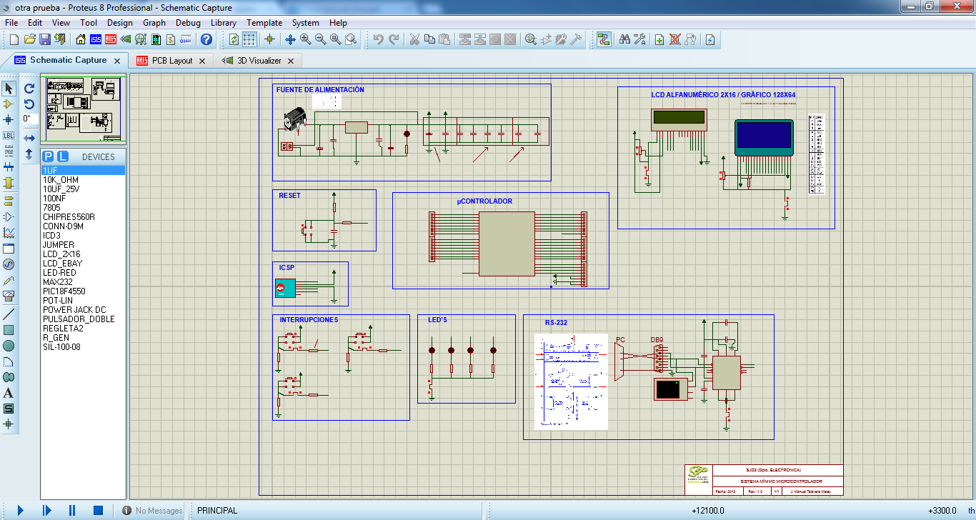
When we just design this, we have to go Ares and connect all to have the final version of our PCB.

Is time to export the archives we will need to use in the CNC program. This archives called GERBER/EXCELLON, and contain the necessary information to the CNC coordinates must follow to make tracks, roads, drill holes...
Click OUTPUT/GENERATE GERBER/EXCELLON FILES and will leave a notice saying this:

Click "Yes", and we will see this:

Click in "Close" and a window appears where we will generate our archives.

We tick archives we want to export and click "Ok". Now we have GERBER/EXCELLON files in the folder we choosen.

Now we have five text documents with the information CNC will need to do our PCB. We have to take all except the "READ ME" archive, and open the next program: Circuit Cam.
When u click in IMPORT, a window like this appear, and u have to select GERBER/EXCELLON files.
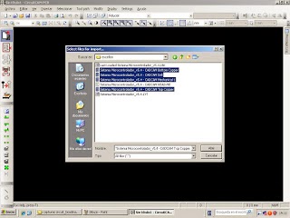
Once selected, a new window appears us with the layers we’ve added, and we will change the “Layer” option, setting the layer corresponding to each file in “File name”, as seen in the pictures.

The next step is click in "Contour routing" and we have to select the layer “Cutting outside”, modified to our liking, we will execute the changes.
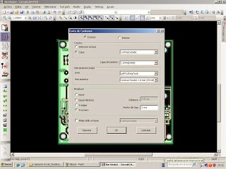
Now click in Tool path/Isolate and first isolation of the bottom, we will leave the default tools, it is important that you have to change the settings to 2mm wide. Finish it to execute the changes and repeat the proccess with the top.

Now open the Board Master 5.0 program and click "Export". The program will open the file automatically.
The first step is put the drill tools in the machine which the program indicate you clicking in the option to open the toolbox.

When we do this, the next step is select the MarkingDrills option, click in "All+" and click Start. The machine will start to do the drill.
When it finish, the next step is click in MillingBottom, "All+" and "Start". When it finish,turn to the plate forward and repeat it with the MillingTop option.
Now we have to select "CuttingOutside" option, click "All+" and Start, and now we have our PCB ready, but without the components.
The next step is to solder the components.

And now we have our PCD ready to use!
No hay comentarios:
Publicar un comentario